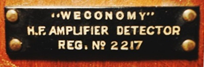
Weconomy Tuner - 1924 - Western Electric Co. (GB) Restoration
 In May 2013, I acquired from an antique dealer in Belo Horizonte City-Brazil a radio receiver built in London in 1924, by the Western Electric Co. Ltd. It is a "tuner" that can be used for further amplification. System works in TRF (Tuned Radio Frequency) and uses two valves 4215AB. The acquisition was a "long shot", since I knew very little about their assembly and operating possibilities. More challenging, like so many others ... The research confirmed my intuition: even consulting the www.radiomuseum.org and experienced friend Konrad Birkner (DE), there were no data on the restoration. The solution was to seek schemes of the first half of 1920 with the same valve to the "gnosis" receiver. In May 2013, I acquired from an antique dealer in Belo Horizonte City-Brazil a radio receiver built in London in 1924, by the Western Electric Co. Ltd. It is a "tuner" that can be used for further amplification. System works in TRF (Tuned Radio Frequency) and uses two valves 4215AB. The acquisition was a "long shot", since I knew very little about their assembly and operating possibilities. More challenging, like so many others ... The research confirmed my intuition: even consulting the www.radiomuseum.org and experienced friend Konrad Birkner (DE), there were no data on the restoration. The solution was to seek schemes of the first half of 1920 with the same valve to the "gnosis" receiver.
1.The Tubes
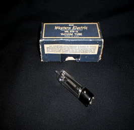
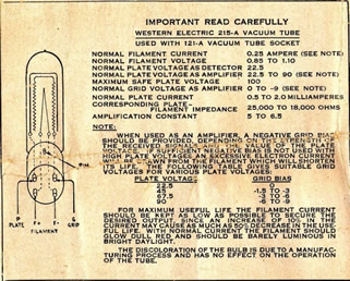
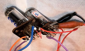
I began to know the valves, absolutely rare and an innovation to the early 1920s: its small size, foreshadowing the famous "Miniwatt" to dominate the market in the 1940s. Valves 4215AB or 215A were first manufactured in 1923 by the Western Electric Co. in the United States. They have only a grid, plate and filament. When I tested those who came in Weconomy a filament was interrupted. Again contacted my friend Howard Stone www.stonevintageradio.com (USA), which sold me two 215A "NOS" (New Old Stock) in the original box and instruction sheet. Main data: Filaments= 1.1V max./0.25A. Plate=90Vmax./2mA.
2.The Scheme
As already said, the scheme was thoroughly searched in the best sites and not found. The solution was unique: making a scheme! But not just copying a schematic wiring, also carrying an understanding of how the receiver works. Put in motion the task of the receiver of the 1920s. Even the name "Tuner" gave the impression of a simple tuner that necessarily needs an amplifier ahead ... The scheme, with reverence by bad designer, is below.
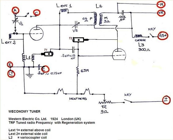
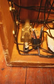 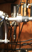
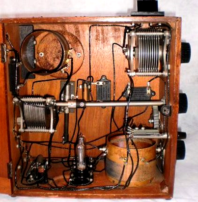
The rarity of 1924, absolutely unusual, had to be analyzed with absolute calm and precision. The circuit is simple, but not so much the doubts! I soon found two pieces containing a pin carbon wrapped in a metal cylinder with a screw. Imagination and experience led to believe on two adjustable resistances, which was not confirmed, since there was no current flowing between the two ends. The brother Darlou's thesis and tests solved the riddle are two "trimmers" of the time, with very small capacitances! Both pieces are marked on the diagram above as T1 and T2. Photos above.
3.The Electrical Restoration
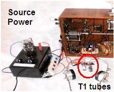
While the order did not reach the valves, replace the other sought to advance the testing. Used 1T4 two valves (Filament 1.4 V / 50 mA.; Plate + B from 45 to 90 V; screen 45-67 V) using only these elements more the signal grid. The supply current for the filaments was done by two ordinary batteries. The B + was supplied by an "old source power" built by late friend Ari Zwirtes from a valve rectifier AZ1. The figures below show the source of B + and the two test valves 1T4.
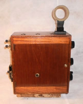
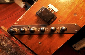
Forward, did the "gnosis" of connecting terminals of Weconomy. As the photos below, "R +" and "R-" = headphones; "45 +" = positive + B (67 VDC), "+ -" =-B and the positive voltage of the filaments; "LT-" and "E" = negative voltage filament. "A" and "C" are external antenna and antenna side, as the reception desired. The hearing was possible with a pair of headphones brand Sterling Telephone & Electric Co. Ltd. (GB), 4 K ohms in serial (2000 ohms each).
  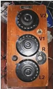
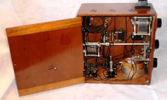
The knobs are arranged in the side. From top to bottom, as pictured above: V2 = variable capacitor antenna (RF); V1 = variable tuning capacitor, R = rheostat voltage wire filaments ("volume") L2 = variocoupler (mobile coils).
Anyway, Weconomy tuned the local broadcast stations in Medium Wave! The best results were obtained with the 67 VDC source + B and the maximum voltage on the filaments of the valves 215-A. Warn that always was careful to use good batteries, but already used, the sum of voltages do not exceed approximately 2.6 VDC: the maximum voltage of the filaments of the valves 215-A is 1.1 VDC each. Overcoming the filaments can burn and produce a great loss!
4. Antenna Coils
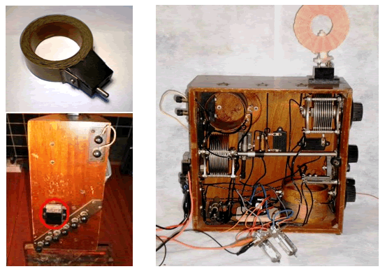
After receiving the two valves 215A from Howard Stone, the reception became more precise and powerful. I made tests with the original external antenna coil side (top left) a 'honey comb’ (L ext2, see scheme). There is a "metal adapter" in Weconomy for the case of a direct link (from "A" to "C") according to the scheme (photo below left). On the top side of the wooden cabinet a "spider coil" was placed in position L ext1, pictured right. I owned it since the restoration of a monovalve model "453" Lindström - Telefunken, 1924. This combination increased the reception and volume, along with the fit of the two "trimmers" (T1 and T2).
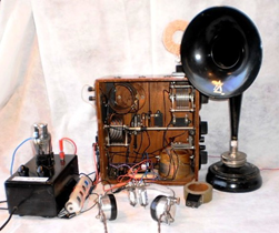
The purchase of Weconomy made in the store of antiquarian Pierre www.antiquedesign.com.br and it included a speaker type "horn". I did tests to adapt it to Weconomy but it produced a very low volume: the impedances need to match: the headphones are 4 K ohms and the "horn" has only 2 k ohms! This challenge will be to hereinafter. Who knows the year and marks the "horn", contact me through the site’s “Contact” page. It has the initials "ZA".
5. Conclusion
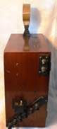
Below are the final photos of the restoration of Weconomy Tuner, Western Electric Co. Ltd., London, 1924.
Daltro D’Arisbo July/2013
www.museudoradio.com |