General Restore and Tags
Tags Most of the receivers no longer have the original emblems or tags. They are fixed in the cabinet, chassis and components and are very useful to model, year and brand identification. These tags have schemes, logotypes, engraved labels or paintings, metal or plastic plates. The absence of them can ruin a receiver value or rarity!
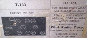 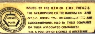
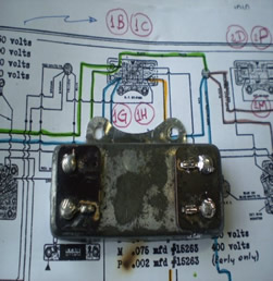
The picture on the right shows a plastic tag on a Marconi brand name radio chassis model T-23BT, made in England by the famous Italian inventor, in 1950. On the left, a Pilot model T-133 paper tag, containing the Tube location.
Never turn on a radio without knowing its features or making sure that there isn’t any short-circuit. After observing the accordance between the original scheme and the chassis, components and wires, the way to test it in what concerns tensions is changing the set’s selecting key to the maximum possible voltage, for example, 240VCA, and turning it on a 110 VCA power supply. This test can also be done using an ordinary 110/220 volts transformer.
Besides the use of multimeters, the traditional test with bulb lamps connected in series to the input cable can also be done. For a good test, should be used a electrical plug protected by a low current spill switch, fast response, six amperes, maximum.
Tips: Turning on a radio for the first time should be done in an absolutely quiet place: the radio may be talking! On the other hand, transformers and other components show listenable signs of tiredness – cracks and noises, before the visible ones: smoke and burning!
Capacitors are a great problem source on old radios. Among them, electrolytic capacitors with leaking or in short-circuit result on the input transformer and rectifying tube burning.
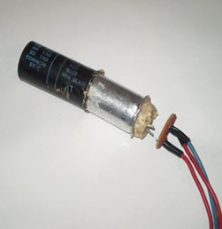
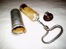 The replacement for other identical one is risky because of the shortage of trustworthy old capacitors. A good practice performed by restoration people is to put new capacitors in the old ones covering. The side picture shows the removal of dielectrical material from an electrolytic capacitor. It’s convenient to use a specific corkscrew to this chemicals and another one just for opening wine bottles... The replacement for other identical one is risky because of the shortage of trustworthy old capacitors. A good practice performed by restoration people is to put new capacitors in the old ones covering. The side picture shows the removal of dielectrical material from an electrolytic capacitor. It’s convenient to use a specific corkscrew to this chemicals and another one just for opening wine bottles...
A careful external heating of the aluminum tube will also give good results.
Capacitors with few mega ohms resistance or with a very different capacitance from the one declared by the manufacturer should not be considered. There is a common sense among people who restore radios concerning capacitors replacement that shows any sign of electrical wastage or even because its covering bad appearance.
The withdrawal of the core former capacitor can also be done by heating. After removal of the cylinder base (contacts and screw terminal), heat gently and turn the aluminum cylinder until you feel that the material inside is loose. Great care must be taken regarding the gases given off by the chemical material of dielectric heating. Use respiratory mask. Below, photos of the "restoration" of the electrolytic capacitor triple (2 x 40 mF + 20 mF) radio Fada (Frank Angelo D'Andrea), 740early model, built in 1947 in the USA.
 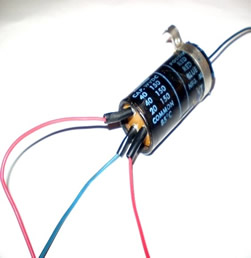
In cases where the electrolyte are not placed in aluminum cylinders on the chassis, which occurs frequently in small receivers and valves in series, it must be exchanged by new electrolytic former directly under the chassis. Below, the replacement of two electrolytic capacitors of 33 mF radio Geloso model G8623, built in Italy in the mid 1950s.
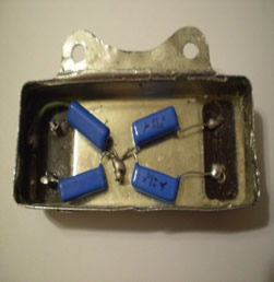
Below, the exchange of common capacitors wrapped in metal housing of the Atwater Kent radio, Model 46, built in 1928 and 1929 in the United States.
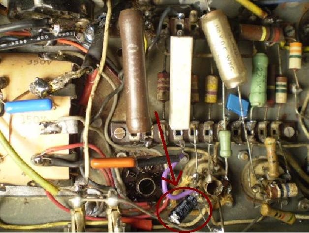
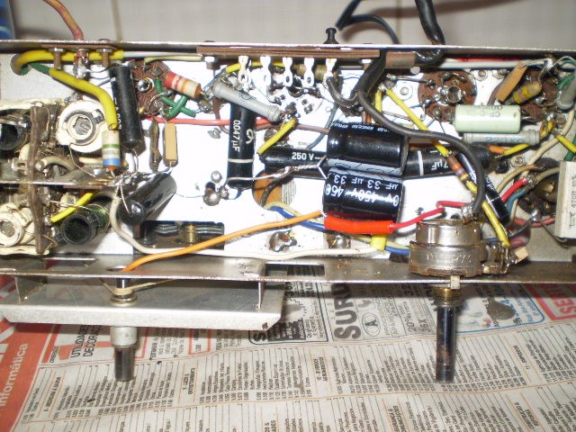
Receptors in old electrolytic capacitors are not only used to "filter" the current rectified. They are also used to "polarize" the cathodes of some valves, among them the output (power). In those cases, it uses a resistance of 200 to 400 ohm 1 watt and in parallel with a capacitor 25 to 50 micro Farads per 25 to 50 volts of isolation. In the photo, one of the electrolyte used in the English radio valve EL41 PYE EP 39B model, the mid-1940s.
Never try to handle or test a radio without making sure to be aware of the electricity risks as well as being totally protected against the danger of an electrical shock! The transformer and the circuit have tensions near or more than 300 volts, what can be harmful to health.
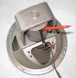
Speakers: In most of the cases, speaker restoration is needed because of the paper cone destruction. There are companies 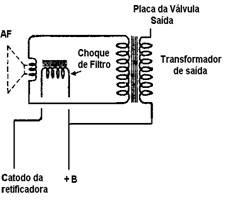 specialized in cone and its coil replacement. Since 1940s, speakers started to be built with a permanent magnet. Before that, speakers were electrodynamic type, magnetized by the current passage through a coil installed on its back part, the so called “filter shock”, on North American schemes, field-coil. Their common values are between a thousand and two thousand ohms. specialized in cone and its coil replacement. Since 1940s, speakers started to be built with a permanent magnet. Before that, speakers were electrodynamic type, magnetized by the current passage through a coil installed on its back part, the so called “filter shock”, on North American schemes, field-coil. Their common values are between a thousand and two thousand ohms.
The side picture reproduces an electrodynamic speaker scheme. It’s important to verify the wire resistance value and continuity of the “filter shock” and audio transformer (output).
Output audio transformers have the primary coil with values between 250 and 450 ohms. On radios with two output tubes, the push-pull, there is a derivation on the primary coil on the audio transformer.
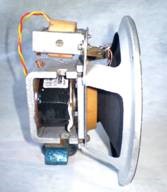
Restoration and painting of a 6, 5 inch diameter electrodynamic speaker of the General Electric radio model K 53, made between 1933 and 1934.
The speaker painting is done under the same instructions used to the chassis: cleaning using a cloth, solvent and a sandpaper number 220 or thinner, and two or three automotive paint coats diluted in paint thinner. All of this should be done in a well-ventilated place wearing masks and gloves.
The most common mistake is to cover the original speakers’ data as brand, number and date.
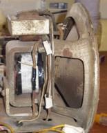 
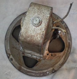
On the picture above, the electrodynamic speaker restoration of a Bosch radio model 516 in 1935. The paper cone was replaced. On the top part of the speaker the output transformer can be seen. It and the filter shock (in black) were interrupted. The finishing was made using aluminum color paint, painted with an ordinary brush.
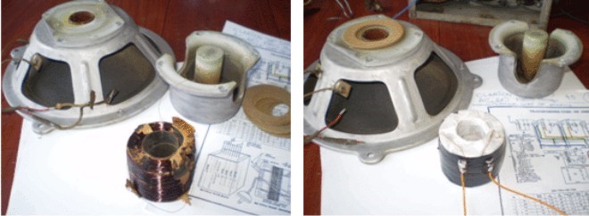 Electrodynamic speaker coil repair. Radio Clarion AC-60, 1930. Electrodynamic speaker coil repair. Radio Clarion AC-60, 1930.
RF and IF coils.The wires of these coils are usually very thin, sometimes as a hair. Its welding deserves much attention. The lack of RF signal or voltage +B occurs very often. May be disruption of RF, IF or dynamic loudspeaker coils. They will have to be restored or replaced. The
replacement of the coil RF or IF is a more difficult case: for a nice operation it should have the same characteristics as before!
Splice and solder a wire of internal coil RF interrupted. Clarion AC-60, 1930.
Tubes The thermionic tube is the old radios` heart, the collectors’ goal. A great part of the problems are on the tube deterioration by time of usage. To measure them, a tube tester and a manual containing its features are used. A simple test using a multimeter verifies the filament continuity. For its replacement, there are specific manuals and free Internet websites.
The simple tube “lightening” is a mere indication of its filament state. There are also times when the indication “good” on the tester covers a weak radio functioning. The analogy between electricity and hydraulics should be remembered: the tube tester only indicates a static parameter. A way to check its functioning, in a dynamic and real parameter, is to put the tube in a working radio which uses the same tube.
 Power Transformers (input) The input radio transformers get the power supply tension, 110 or 220 volts, supplying it in different values to the circuit needs.They usually have low-tension outputs of 2 to 6 volts to filaments and lamp bulbs feeding. To high tension the values are between 200 to 300 volts. Power Transformers (input) The input radio transformers get the power supply tension, 110 or 220 volts, supplying it in different values to the circuit needs.They usually have low-tension outputs of 2 to 6 volts to filaments and lamp bulbs feeding. To high tension the values are between 200 to 300 volts.
On the picture to the right, a power transformer Philips type, to tubes with 4 volts filaments, at identification and testing stage. One good source to get these transformers is the wasted chassis from radios which restoration is difficult or the cabinet is not found. Another way to solve transformers’ problems is redoing its coiling. On the electronic part restoration it’s common to find this transformer burned
or in short circuit. It’s very important to be extremely careful with this
component, not only because its first function on the radio but also for the high risk
of burning the rest of the circuit.
Tips: After unplugging the radio plug from the socket, with the multimeter on the resistances’ measurement scale (?), the plug prong to prong value is measured, always with the device unplugged from the house power supply.
The resistance value with the radio connecting knob on the off position must be zero; other values indicate problems, for example, the short circuit. Position on, the resistance must show values between 5 to 20 ohms with radios working at 110/127 volts.
If it’s zero, cable continuity and connections, the volume control and the transformer itself must be checked. Some transformers in good state, covered with a thinner wire, can show values from 20 to 30 ohms.
Knobs
The knobs and dial are the "face" of the radio. The original buttons are increasingly rare and expensive, sometimes had to be built. The wooden buttons of the old models of chapels or tombstone cabinets can be made on a lathe for wood. The remaining synthetic knobs can be made with the same substances used for dental prostheses. In the photo to the left, the mold, the original black and orange knob made. At the center, the first coat of black paint and a brass bushing to be secured to the shaft. On the right the two knobs, belonging to Emerson Radio Model 547, built in 1947nos USA.
  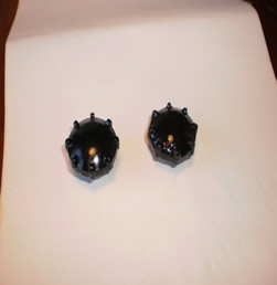
One of the buttons of this receptor Zenith model 6S321, built in 1937 in the USA, was made by a friend the dentist. In the picture it is very difficult to figure out which is such perfection "!
 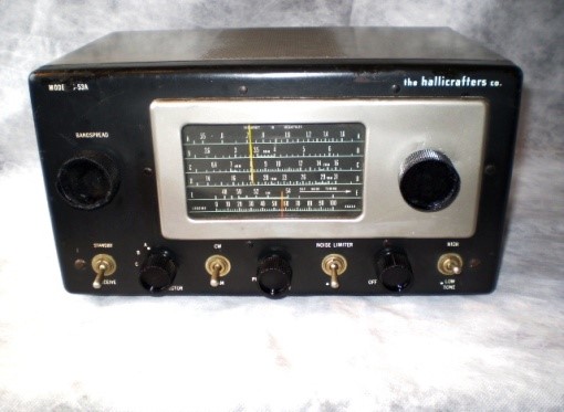
On the right side a Hallicrafters Model S-53 th with the left made. This is easier to be identified!
Daltro D’Arisbo
Radio collector and restorer |