Radiola 26 - 1925
Restoration
My thanks to everyone who helped me, without whom it would have been impossible to make the Radiola 26 work as new.
To the radio collector and technician Konrad Birkner www.radiomuseum.org; to the salesmen at Howard Stone www.stonevintageradio.com; to Gary Schmidt www.oldradioparts.com; to the collector and restorer Richard Fairbanks, www.pharoahaudio.com/radiola26part1.html; and to the website www.cfp-radio.com/restaurations/radiola26/chapitrage-radiola26-EN.html for all the valuable information. Last, but not least, all my longing and consideration to my beloved late friend professor Ari Zwirtes who, despite being seriously ill, built the chassis to the DC source of the Radiola.
Daltro D’Arisbo
Dec/2011
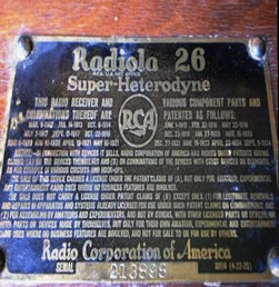
Radiola 26 RCA - 1925
In 2011 I bought a Radiola 26, one of the first super heterodyne manufactured by RCA in the United States, from Don Hugo, an Argentine living in Brazil. After an initial examination, I noticed that there were damaged valves in the receiver as well as some missing components, as a rheostat and its knob. As for its operational conditions, a voltage test was unthinkable. First, because this is one of the last steps of the examination; second, because it runs on four different DC voltages: 3V for the filaments, 90V and 45V for the plates and -9V for the volume grid circuit. There should be a source with such different voltages. Furthermore, originally early radios ran on batteries which no longer exist.
That would be a challenging job. I had never fixed or even opened any other equipment with such characteristics, so I had to convince myself not to give up. First, it was essential to find the layout, enlarge it, identify and study the different circuits. Then, open the Radiola, removing and isolating the main components, namely loop antenna, chassis, catacomb, speaker and wood cabinet.
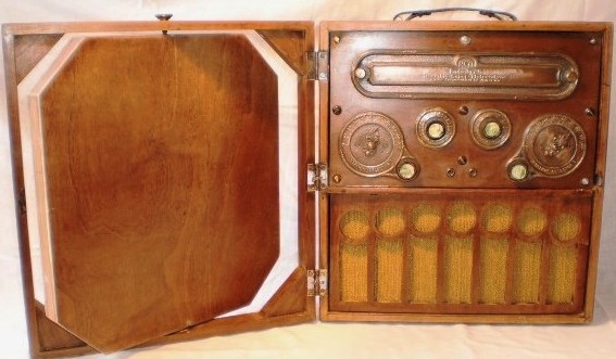
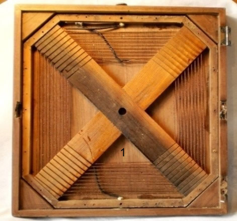
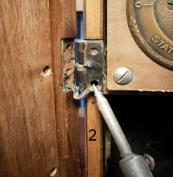
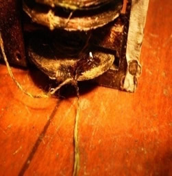
1. Cover and loop antenna. Radiolas have an antenna coil (the first RF transformer) inside the cabinet (1). This "cap-loop antenna" turns on two pivots, providing a better reception. RCA anticipated the directional antenna in three decades. Removing the frame cover, one can see the coil. The connection between the two ends of this coil inside the receiver is made through two steel meshes welded on two bottom hinges (2). To unlock the whole cap antenna of the Radiola box it is necessary to break the welds. Only then can the screws of the three hinges be removed.
  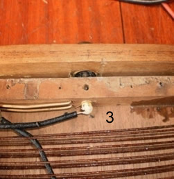
“An old radio has always been fixed before…” This one was no exception. Unfortunately, an uninformed amateur replaced the coil frame in an inverted position within the frame: the ends of the coil had no contact with the disc of the lower pivot (3). Thus, they were not connected to the chassis. So it was necessary to unscrew the two pivots, remove the frame, clean the contacts thoroughly and set them up correctly. After this kind of procedure it is important to check the continuity at the ends of contacts.
In this case, it is essential to check the existence of perfect contact from the wires attached to the lower pivot hinges, even when the coil turns, as well as to test the electrical continuity between the internal circuits and the hinges with the cap loop antenna.
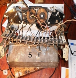
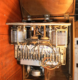
2. Dismantling a Radiola. The withdrawal of the entire circuit was a rediscovery of the old radio. The circuit can be divided into two parts: a "chassis"- shaped rectangle containing two variable capacitors, two FI coils, two rheostats and a contact bar (4); and the catacomb, which is a closed can at the bottom of photo 5. The top of the catacomb is closed by a plate of bakelite where the valves are placed at the top of photo 4.
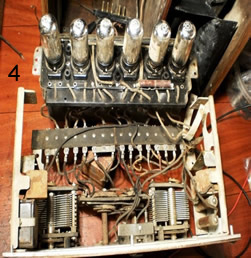 
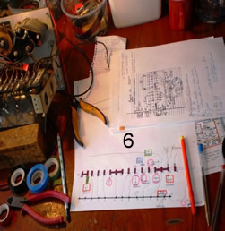
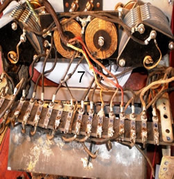
The dismantling and recognition of the circuit should be carried out with the utmost caution, with a written description of all the connections and its correspondence with the original circuit. Letters, numbers, drawings and sketches are indispensable (6 and 7).
I started the cold tests without connection to any electrical potential. All capacitance and resistance values between terminals and valve seats were checked throughout the electrical wiring and compared to the original schema.
The results were not good: there was interruption in the transformer T1 connected to the power tube and several capacitors had wrong insulation and capacitance. Conclusion: the can would have to be fully open and the pitch involving the components of the vault would have to be melted, a task as difficult as digging in a graveyard...
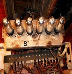
3. Withdrawal and opening of the “catacomb”. As many receivers from the late 1920s, the Radiola 26 has most of the wiring and components such as transformers, capacitors, coils and resistors, in a tin, which is covered by a Bakelite board with sockets of the valves. This component is the catacomb, name that became popular among technicians in the USA in the 1920s and 1930s. In addition to being sealed by metal casing, all these components were also wrapped in a “brick" of pitch. The hermetic seal protected the chassis, preventing moisture and, what's more, unauthorized copy. It was motivated by the purchase of the patent of the super-heterodyne by RCA from Edwin Armstrong, its inventor.
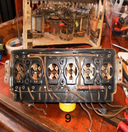
While disassembling the catacomb, I removed the metal cover plate that covers the bakelite, which contains the sockets of the six valves (8 e 9).
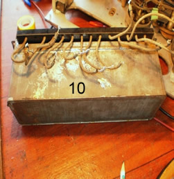
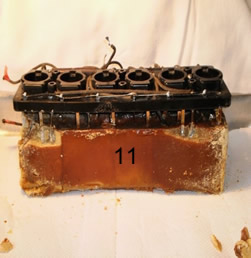
In the meantime, my friend Howard Stone, an experienced American restaurateur, defined my intent to melt the pitch in a few words: You’re a brave man! The following photos show the process. Once the catacomb was isolated from the chassis (10), the core, made up of a block of pitch involving all the components, became visible (11).
The next step was to melt the brick pitch to find the breakpoints circuit and capacitors damaged by 86 years since its manufacture!
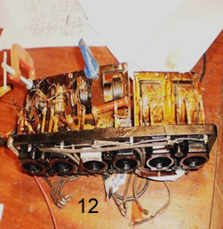
The withdrawal of the pitch was done carefully and outdoors, for its harmfulness. Due to the heat, the procedure did not spare the interruption of a few threads of the coil. Photo (12) shows how the circuit was removed from inside the mantle. Unluckily, it was damaged: there was a crack in the bakelite plate, which meant a lot more work ahead!
 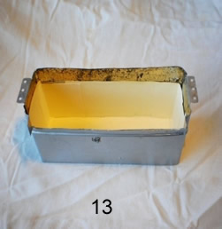
The wrap around the catacomb was recovered with a painting and lining paper for the isolation of likely short circuits (13). After all, the whole Radiola chassis and wrapping around the catacomb are connected to the positive pole of battery "A" (3 VDC filaments) and to the negative pole of battery "B" (90 e 45 VCC).
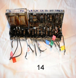
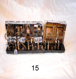
4. Restoring the catacomb and the chassis. The removal of the catacomb was also performed with attention in order to identify the circuits and their associated wiring. In addition to the original numerical order of the circuits, colored tapes were used to facilitate identification (14 e 15).
Soon it was clear that the coil L1 was fragmented into four parts, as five different tips of wires came out of it: two normal wire ends and 3 more in the center of the winding. Trying to rebuild it would be insane: it has the shape of a big coin, thin and flat. After measuring it I decided to connect the ends that had similar values to the one indicated in the scheme. The photo on the right shows the tiny point of the weld seam.
Instead of the original 33 ohms, it was possible to get 15 ohms, less than half the original value of the resistance! However, as these historical and high quality radios do not reach critical values for certain stages in the circuit, making it work became an obsession.
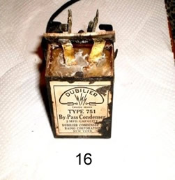
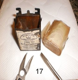
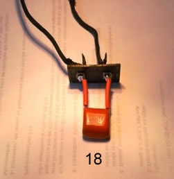
The other connections were correct, I just had to change some common capacitors, all altered and with capacitance values greater than the schema: C5 (50pf), C7 (200pf), C8 (50pf) and C9 (240pf). Capacitors with value higher than C10 and C13 (0.01 μ) were replaced, as well as the Dubilier filter C11 (1 μ), which was kept in the original wrapping (16 to 18).
The "output transformer", a silvery, flat and cylindrical body (resembling an UFO!) placed next to the speaker, indicated continuity and resistance of 2,000 ohms. Compared to all the hassle reported by other restorers, this fact caused great enjoyment.
The chassis was measured so as to check the continuity in the Transformers Intermediate Frequency (IF) (2.1 and 2.6 ohms) and in the variable capacitors C1 and C2, with amplitude varying from 81 to 765pf. The following items were also checked:
1. Antenna circuits, starting from the antenna coil (detachable lid), C1, C3, C5, C6 and L1;
2. Oscillator circuit: C2, C4, L9 and L10;
3. Circuit boards and rails and related transformer;
4. Circuit "A" (filaments). Point A + is trapped inside the can that surrounds the catacomb;
5. Circuits "B" (90 and 45 VDC) and "C-" with the terminals of the valves.
Chassis and catacomb connected and ready
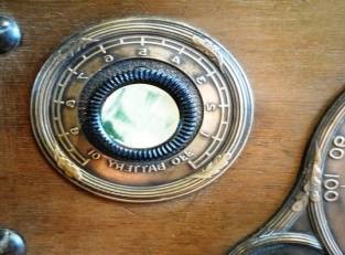
5. Rheostats e Knobs. The Radiola 26 has two rheostats connected in series and operating in the circuit "-A". The one called Volume controls the tension on the filament of the 3rd valve and the called Battery works in the other five valves. There was another difficulty: I had acquired an incomplete Radiola, without one of the rheostats and its brass plate. The only solution I could find to replace the absent rheostat was to adapt a conventional 50-ohm potentiometer. The plate and the knob were purchased from Gary Schmidt (USA). Then a picture of mother-of-pearl was glued to the center of the knob, as it had originally been manufactured (right below).
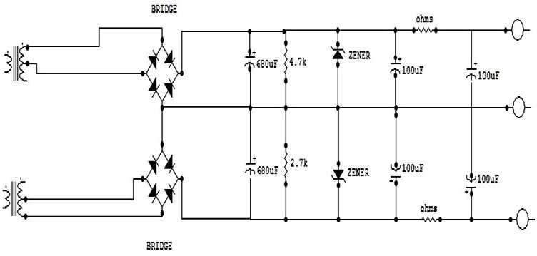
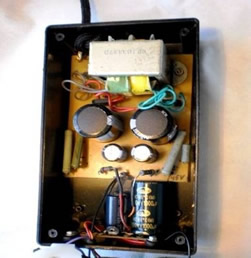
6. Source. A source of discharge current (Batteries "B") was built to feed the Radiola as shown below. It is made up of a transformer (although there seem to be two) with a primary entry to 127VCA and two secondary entries: 125 and 55VCA. Two "bridges" and two electrolytic capacitors 680μ make the adjustment. Two Zener diodes control the voltage resistance of 4.7 and 2.7 k? (20 W and 10 W) for heat dissipation. In addition, two more sets of electrolytic capacitors 100μ are interspersed with small value resistors to adapt the filtering. The output voltages, with the source in use, were 92 VCC and 42VCC. The diagram shows no-charge values and the voltage ratings in parentheses.
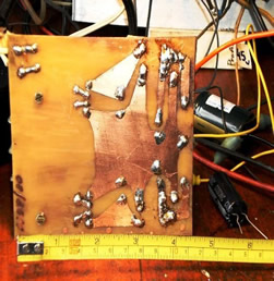
The completion of the source was basically finished by my beloved late friend Ari Zwirtes www.radioantique.com.br. He built the chassis with a printed circuit board (photo). To power the filaments of the valves (Battery "A" 3 V), I took into account the advice from Konrad Birkner and his warnings of the risk of burning the filament strands.
Built from 1922 on, the rare and expensive valves UV199 heat the filament with very low current (60-63 mA) and with a very low tolerance - only 10% - to the voltage increase (3 to 3.3 VDC). If I used the rectification of AC current to power these filaments, it would greatly increase the danger of breaking them, even using limiters (Zener). Hence the decision to place two large alkaline batteries in series: besides supplying the purest continuous current, they will never overcome the 3.3 VDC. As for the plaque of UV199, it works with a potential of 90 VDC that tolerates variations up to 95VCC, for example.
For Battery "C" (9 V), again Konrad Birkner's knowledge was of great value. With a small negative voltage on the grids, or even without it, the Radiola would work. It actually happened, but the replacement of this battery for an electrolytic capacitor 33μ x 25 V greatly increased the reception, making it totally redundant.
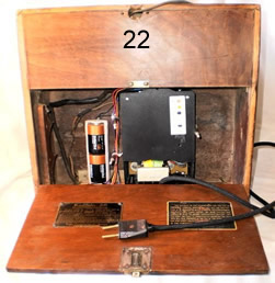
The schemes www.pharoahaudio.com/radiola26part1.html were also essential in the search for information for the construction of the source. Thus, the source built fuels only the tensions of batteries "B", a simplified solution that meets very well the Radiola 26`s operational needs. In the end, the whole
set, the source and support of the batteries, was attached inside and on the back of the Radiola, the same place where the original batteries had been originally placed (22).
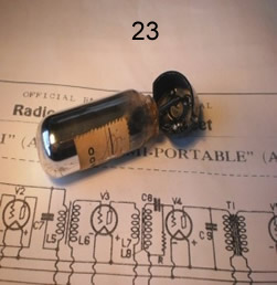
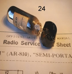
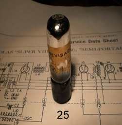
7. Valves UV199 e the Test. When I bought the Radiola it came with its 6 original valves UV199. However, two valves’ bases were disconnected from the wiring bulb. I tried and managed to reassemble them (23 to 25).
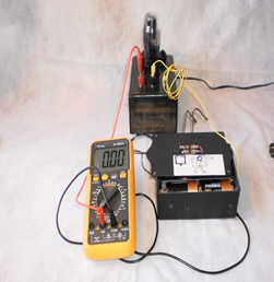
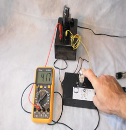
But how to test a valve which had been manufactured between 1922 and 1925? If one does not know the answer, one must ask and learn! My friend and collector Sergio Caon presented a simple scheme for the verification of UV199. All we had to do was to apply a voltage of 3 VDC on the filaments and another one, positive, of approximately 90VCC, on the plate. It was necessary to charge it (e.g., an output transformer) and then measure the current emission. However, since there was no extra socket to the valve, phenolite strips were used for connections.
The scheme below contains a multitest on a scale of 20 mA DC, an output transformer of 200 x 1 ohm, 2 large alkaline batteries and a source of 90 VDC. Out of curiosity, a speaker can be connected to reproduce the signal. In the grid position, a negative potential or a sign can be connected, but it is not necessary.
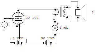
To obtain the 90 VDC voltages a source built by Professor Ari Zwirtes with a valve AZ1 was used. I always use it to test very old equipment. It appears at the top of the photos. An approximate value of 4 mA indicated the valves in regular conditions for operation.
8. Final.
After four months working most evenings and days off, the Radiola 26 was ready for its first real test under tension. It seems important to emphasize that during these 120 days the whole work was done with "cold" electrical components, with measurements of continuity and resistance only. There was a connection to the current source only on the "Judgment" day. That's when the RCA Radiola 26 operated in a satisfactory way for the first time, broadcasting an AM radio station and great emotion.
It was recorded a small video showing how Radiola 26 works. In it I thank all those who helped me in this work. Sorry about the language mistakes. http://www.youtube.com/watch?v=aHi7kVCui94 |